_1795230047287.webp "3D Folded Geometric Irregular Aluminum Ceiling Panels")
_1795230047342.webp "3D Folded Geometric Irregular Aluminum Ceiling Panels")
3D Folded Geometric Irregular Aluminum Ceiling Panels






- Product Description
Using two real project photographs as samples, this article unpacks the full decision chain of 3D folded aluminum ceilings, from geometric logic and structural systems to bending process and site acceptance, and sets out parameter boundaries that can be used directly for drawing development and factory ordering. All figures are industry experience ranges and must be confirmed by a physical mock-up for each project.


1. What This Product Actually Is
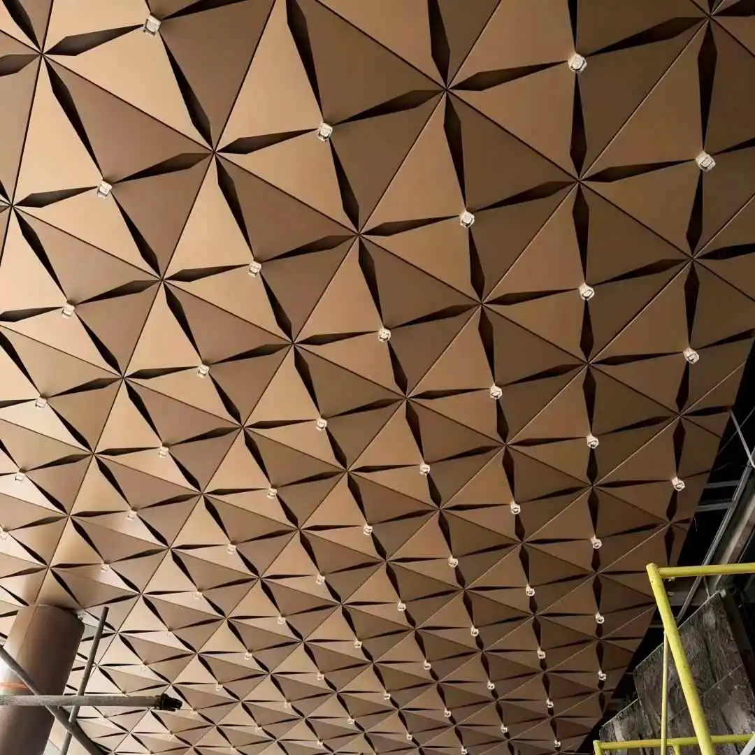
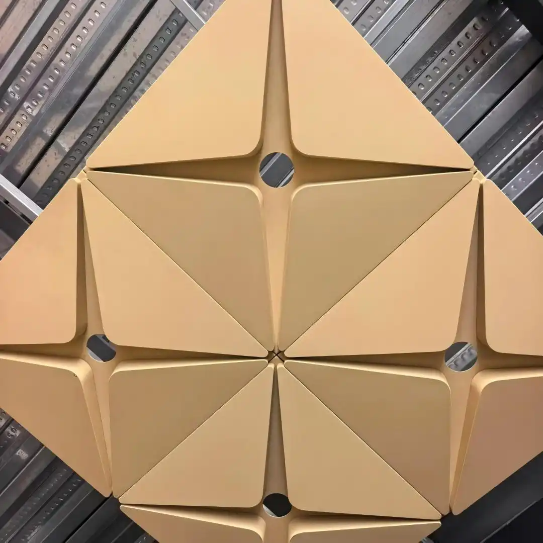
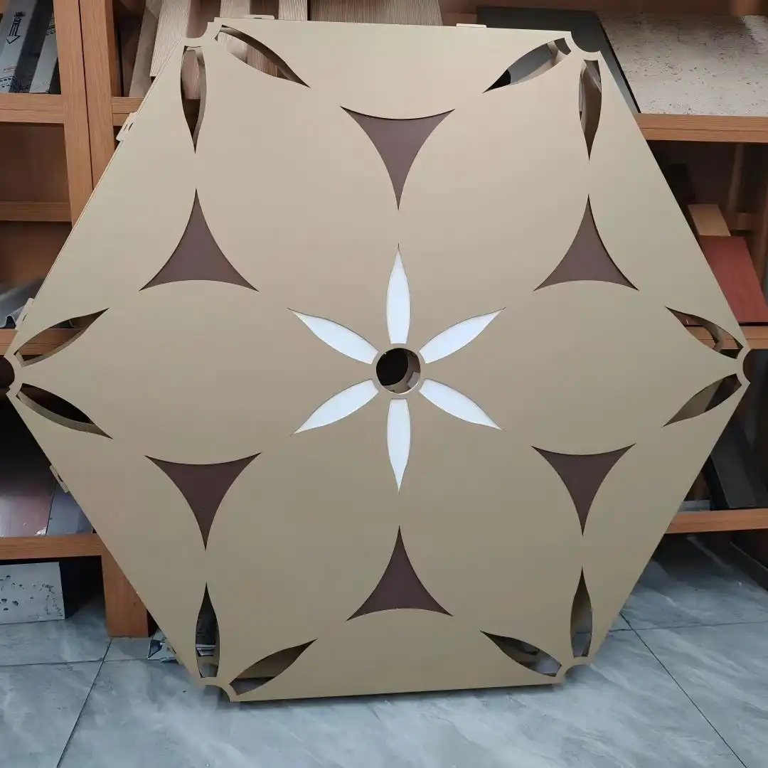
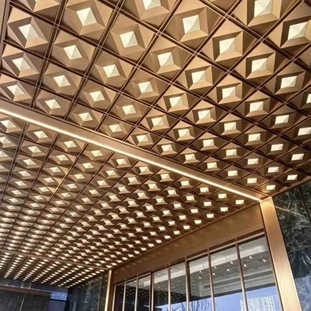
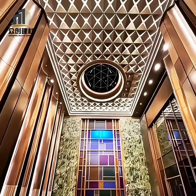
An irregular aluminum ceiling is not a flat panel that has been bent once. It is a system in which non-planar geometric units are formed by CNC bending and then assembled into a continuous surface. This article focuses on the most representative type: the triangular-facet geometric ceiling, where each visual unit consists of four to six triangular faces enclosing a raised or recessed pyramid, and these units combine into hexagonal or diamond grids.
A complete system has five parts, and all five matter:
-
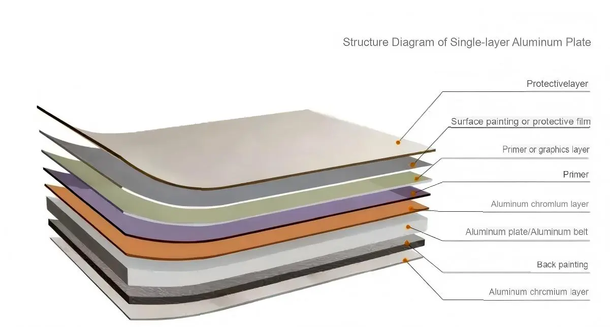
Facet panels: the visual body, usually 1.5–2.5mm aluminum sheet with folded edges for interlocking or fixing
-
Load-bearing frame: either frameless interlocking, where folded edges transfer load, or a frame system built from I-beam aluminum profiles or square tubes
-
Connectors: corner brackets, self-tapping screws, bolts or clips, which determine serviceability
-
Perimeter system: custom transition pieces at walls, light coves and curtain walls, often requiring separate tooling
-
Surface finish: PVDF coating, powder coating or anodizing, applied after bending is complete
Frames and connectors are the two items most often cut during cost reduction, yet they are exactly what determines whether the ceiling sags, rattles or opens at the joints three to five years later.
2. Fold Angle: The First Variable That Decides the Result
The same triangular unit produces three entirely different products depending on its fold angle. Here the angle means the angle between the facet and the horizontal datum; 15°, 30° and 45° are the three common specifications.
|
Fold angle |
Visual character |
Suitable ceiling height |
Process difficulty |
|---|---|---|---|
|
15° (shallow) |
Soft light gradients; reads almost flat from a distance and only reveals its facets up close. Suited to lobbies and galleries that need a quiet ceiling |
Above 3.5m |
Low; standard press brake is sufficient |
|
30° (standard) |
Clear contrast between lit and shaded faces; the hexagonal outline is immediately legible. The most widely used specification and the best balance of character and buildability |
3–6m |
Medium; dedicated tooling required for angle consistency |
|
45° or steeper |
Close to a true pyramid. Shadows are dramatic when viewed from above, but people walking underneath feel visual pressure and may experience dizziness during long exposure |
Above 6m or decorative only |
High; cracking risk at the fold, requiring annealing or multi-stage bending |
How to judge: a steeper angle does not automatically mean better design. In a space with a 3m ceiling, a 45° fold gives people underneath a field of dense sharp points rather than a sense of geometry. Set the angle from the ceiling height first, then size the unit: the lower the ceiling, the shallower the angle and the larger the unit.
One fact is routinely overlooked: the same facet reads as convex from below and concave from above. This is why renderings, which are usually viewed from above, so often fail to match the finished ceiling seen from underneath. During design development, check a 3D model from the upward-looking viewpoint rather than relying on a flat layout drawing.
3. The Divide Between Two Structural Systems
The two photographs represent two genuinely different technical routes.
|
Item |
Frameless close-joint (dark sample) |
Frame-supported grid (white and black sample) |
|---|---|---|
|
Load path |
Folded edges interlock; load travels along fold lines to secondary battens |
I-beam aluminum grid carries load; panels are bolted to the frame |
|
Joint width |
2–3mm, concealed by the shadow of the fold |
8–12mm expressed joint, which becomes part of the design |
|
Substrate tolerance |
Strict; deviations over 5mm become visible |
Moderate; the frame can be leveled independently |
|
Panel removability |
Poor; panels must be dismantled from the perimeter inward |
Good; individual panels can be removed for maintenance |
|
Relative cost |
Baseline |
15%–25% higher |
|
Best use |
High-end hotels, clubs and showrooms where a seamless surface is the goal |
Public buildings with services above the ceiling and regular access needs |
How to choose: if there are air ducts, sprinkler pipes or driver boxes above the ceiling that require regular access, choose the frame system. A close-joint ceiling looks better, but a single maintenance visit means removing a large area, and reinstalled panels rarely return to the original joint width. This needs to be agreed with the client at the tender stage; otherwise it becomes a dispute after handover.
4. The Layout Trap: Why Identical Orientation Opens the Joints
This is the most common failure in triangular ceilings and the point where factories and designers most often blame each other.
A hexagonal honeycomb is enclosed by six triangular units. Each unit is either left-handed or right-handed, meaning the direction its facets face. If every unit in a ceiling is oriented the same way, the shared edge between adjacent units shortens by roughly 1–2mm after bending. Across hundreds of units the error accumulates, and a 2mm design joint becomes 5mm or more, clearly visible and impossible to correct by adjusting the frame.
The correct method is mirrored alternation: left- and right-handed units are paired so that shared edges coincide exactly and joint width stays at the design value. Development drawings must distinguish the two orientations by color or mark, and the factory must produce them in matched pairs by number.
Inspection method: take two adjacent units at random, place them face down and check whether the two edges fit together completely with no wedge-shaped opening. This test is more reliable than any visual inspection of the finished ceiling.
5. Light and Geometry: A Misplaced Luminaire Flattens the Form
Both photographs share one detail: the luminaires sit at the vertices of the hexagons, not at the centers of the facets. This is geometric logic rather than aesthetic preference.
-
Light at the vertex: illumination spreads diagonally across the facets, strengthening the boundary between light and shade at every fold, so the geometry stays crisp
-
Light at the facet center: the hotspot lands in the middle of the triangle, washing out the fold lines and flattening the relief
-
Light between units: creates a continuous band of light that cuts across the form; suitable when the design emphasizes lines rather than volumes
Dark and light finishes also need different lighting strategies. Light colors such as white are read through shadow and need side or angled light; dark colors such as brown or charcoal are read through specular highlight and need light close to directly overhead, with glare control. Dark panels also absorb more heat, so under semi-exposed conditions or beneath a glass roof the surface runs hotter than a light finish and the coating system must be upgraded accordingly.
Luminaire positions must be frozen with the electrical discipline during design development. Building the ceiling first and cutting light holes afterwards is the single largest source of rework on these projects: once a hole lands on a facet, the fixture either protrudes or sits recessed and the geometry immediately fails.
6. Bending and Coating: Get the Sequence Wrong and the Fold Shows White
Whether the fold line stays sharp depends on two process details.
|
Process item |
Correct practice |
Wrong practice and consequence |
|---|---|---|
|
Inner bend radius |
Keep within 0.5–1.5mm so the fold stays sharp and the shadow boundary clean |
Radius above 2mm turns the fold into a bright band and weakens the geometry |
|
Coating sequence |
Bend first, coat afterwards, so the film remains continuous across the fold |
Coating before bending stretches and cracks the film at the fold, exposing bare aluminum. This is the clearest tell-tale |
|
Number of bends |
For folds beyond 45°, bend in two stages to avoid cracking |
A single full-depth bend tears the outer grain and later blisters or cracks |
|
Sheet thickness |
1.5–2.0mm for unit edges up to 600mm; 2.5mm for larger units |
Using 1.2mm throughout to save cost produces oil-canning on large facets, visible as waves in reflected light |
Site check: hold a phone torch flat against the fold and shine it along the line. A thin white line or fine crack indicates coating before bending; a continuous, evenly colored film indicates the correct sequence. No instrument is needed, so buyers can apply this test during incoming inspection.
7. Installation and Acceptance: Three On-Site Checks
A 3D folded ceiling cannot be accepted against the flat-panel standard of visual flatness. Use the following three checks.
|
Step |
Action |
Acceptance criterion |
|---|---|---|
|
Head-on view |
Stand directly beneath a unit, look up and walk the full area in one direction |
Joints of the same type are consistent in width with no sudden wedge-shaped gaps; no flipped or misaligned units |
|
45° oblique view |
Observe the facets from an oblique angle |
No oil-canning or distortion; fold lines in the same row align on one straight line |
|
Backlight test |
Switch off all lighting and shine a torch upward from below |
No light leaks or open joints; light-hole edges sit flush against the facet with no lifting |
Installation sequence matters: start from a central datum unit and work outward radially, finishing at the perimeter. Laying panels progressively from one corner accumulates all the error at the opposite edge, where closing becomes impossible. Starting at the center distributes tolerance evenly in all directions.
Dust note: upward-facing concave facets are natural dust traps, especially in semi-open spaces. Design them to face downward, or make the units removable; otherwise the ceiling becomes a dust display within two years.
8. Where It Works and What to Specify
This product does not suit every space. A practical breakdown:
-
Best fit: hotel lobbies, brand showrooms, commercial atria, theatre foyers and airport VIP lounges, where ceiling height exceeds 3.5m, a strong visual identity is wanted and maintenance access is infrequent
-
Workable: office lobbies, sales centers and flagship stores, preferably with a 30° fold and a frame-supported system to balance appearance and serviceability
-
Not recommended: corridors below 3m, hospital wards and school classrooms, where dense sharp angles create visual pressure and cleaning dead zones
Six parameters to freeze before placing a factory order:
-
Fold angle and unit edge length, which determine tooling and sheet thickness
-
Handedness ratio and layout drawing, which determine whether joints open
-
Structural system: close-joint or frame-supported, which determines cost and serviceability
-
Sheet thickness and alloy grade: 3003-H24 is common indoors, 5052 series is preferable outdoors
-
Coating system and film thickness: 60–80μm powder coating indoors, PVDF topcoat of at least 25μm outdoors
-
Luminaire coordinates and cut-out sizes, which must be coordinated with the electrical drawings
9. Frequently Asked Questions
Q1: How large can an irregular triangular aluminum ceiling be? Is there a limit?
Individual unit size is limited by sheet thickness and bending capacity, with edge lengths typically not exceeding 1200mm. There is no hard limit on total area, but ceilings above 500㎡ should be divided into zones with expansion joints to prevent accumulated thermal movement from lifting the perimeter.
Q2: How much more does it cost than a standard aluminum clip-in panel?
On the same area basis, the combined material and labor cost is usually two to three times that of a flat panel system. The difference comes from three sources: bending hours, dedicated tooling, and the stricter substrate requirements during installation. Shape complexity and fold angle are the main variables.
Q3: Can it be made removable?
Yes. A frame-supported system already allows individual panels to be removed. A close-joint system can be made removable by adding elastic clips to the panel backs, which adds roughly 10% to cost and makes joint-width control more difficult.
Q4: How does it perform in a fire?
Aluminum alloy is itself non-combustible. With an inorganic coating system the product can reach GB 8624 Class A (A2-s1,d0) or EN 13501-1 A2-s1,d0. Note that if the coating cracks at the fold, the assessment is made on the as-built condition and the classification may be affected. Bending before coating is therefore a compliance issue, not only an appearance one.
Q5: What is the typical lead time?
Allow 20–30 days from approved development drawings to first shipment; add 7–10 days if new tooling is required for the shaped units. For large areas, ship in batches of 300–500㎡ matched to the installation sequence to avoid deformation in storage.
For project-specific drawings, mock-up samples or a formal quotation, contact Guangdong Zhongchuang Architectural Decoration Materials Co., Ltd.
_1782530506402.webp)
(1)_1783045836766.webp)
_1786157639392.webp)
(1)_1780970038980.webp)